

Updating and development
of beer process flow diagram
Viravix Engineering offers P&ID and PFD updating and development services. P&ID and PFD are necessary during the planning of equipment modernization works, in particular, the finding ways of energy consumption reducing.
What is P&ID and PFD?
To control the technological process the diagrams are used. They clearly show what elements are included in the system and how they interact with each other.
PFD (process flow diagram)
The general scheme of the technological process shows the main equipment involved in the process and the flows of materials and raw materials.
The PFD clearly shows the interaction of components in the technological process. Therefore, it is often used as a basis for planning improvements, as well as for training job newcomers.
What can PFD contain:
- the main equipment;
- technological pipelines;
- basic designations, names and identification numbers of equipment;
- controllers, valves and critical valves affecting system operation;
- interconnection with other systems;
- main, reserve and recirculation lines;
- system nominal and operating values such as minimum, normal and maximum flow,
- temperature and pressure;
- composition of liquids in the system.
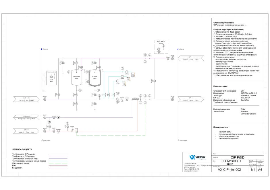
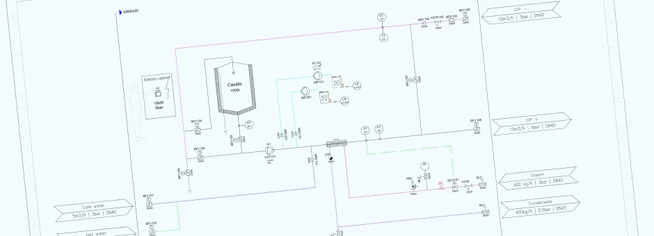
P&ID (Piping & Instrumentation Diagrams)
This is literally “scheme of pipelines, pipeline fittings, pumps, control and measuring devices”.
P&ID is more detailed than PFD. P&ID is often used by technological engineers, KVP specialists, and operational personnel.
What can P&ID contain:
- measuring devices and their designations;
- mechanical equipment with names and numbers;
- all valves and their designations;
- technological pipelines, their dimensions and identification
vents, drains, special fittings, sampling lines, reducers, expanders and samplers; - permanent start-up and flushing lines;
- flow directions;
- interconnection link;
- control inputs and outputs, blocking interfaces;
- input data;
- other data regarding the customer’s needs.
Flows of liquid, materials, raw materials are marked with arrows on both diagrams; with symbols — main and supporting equipment. A chief engineer or technical manager will need both options to manage the technological process.
Why do you need drawings?
Where are P&ID and PFD used
- design and layout of the industrial process;
- development of the equipment specification;
- development of control algorithms and schemes;
- HAZOP (hazard and operability study) — hazard analysis and analysis of system operability;
- technical operation;
- planning of repairs, replacement, modernization of equipment;
- development of production regulations, instructions, process maps;
- training and retraining of operators of the technological process (system);
- visualization of the process in the automation programs.
What is required for the development of P&ID and PFD
- Computer-aided design (CAD) software compatible with enterprise drawing requirements.
- Lists of technological process components.
- Description of the input and output of the main and auxiliary streams.
- Equipment location dimensions.
- Identification signs of all components in accordance with the system adopted at the enterprise — the drawings must be understandable to users.
- Types and characteristics of materials used.
- Power balances for each line
Detailed P&ID and PFD are necessary for calculating the costs of raw materials and planning energy-saving actions.
Development and restoration of P&ID and PFD are repetitive process. For effective control of the technological process the drawings are updated with the frequency established in the industry, and as well after each equipment replacement.
Work stages
1.Data analysis
- collection of initial data on existing processes at the enterprise, equipment inspection;
- study of customer documentation, drawing requirements and project management;
- analysis of the initial data
2.Designing
- PFD Development – schemes of the technological process;
- P&ID updating;
- equipment technical specifications development;
- technical data tables preparation
3. Customer check and submission of work results
in accordance with the requirements of the technical task
Specific deadlines and work content for P&ID and PFD updating (development) are specified in the technical task of the contract.
Who are we?
“Viravix Engineering” — is a team of food processing industry engineers.
Each of our specialists has made the way from ordinary equipment maintenance worker to zone engineer, which is engaged in the work of 10−20 factories.
Our partners:
Elaks, Krones, Zipbier, KHS, Alfa Laval, GEA
Our clients:
Heineken, Mondelez, Nestle, Unilever, Bunge