


26.10.2026
How
Study
Plate Heat Exchanger Calculation for Food Processing: What Data Is Needed for Selection?
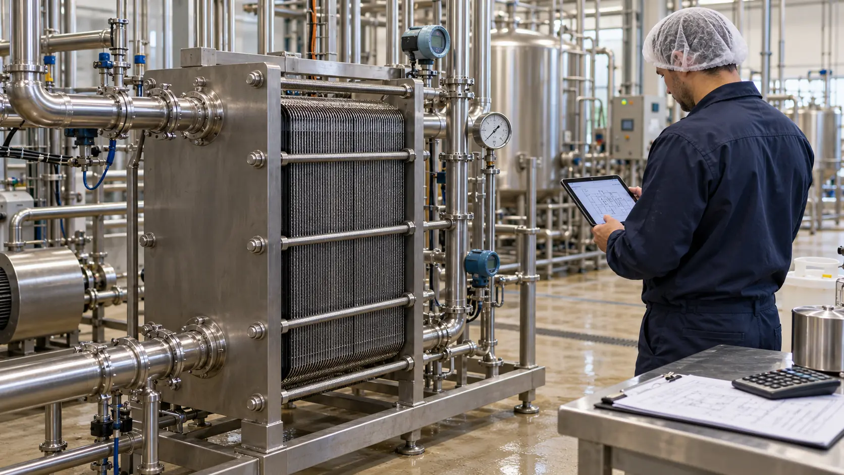
A request for “a heat exchanger handling 10,000 L/h” is not enough to select the equipment. At the same throughput, milk, cream and sugar syrup require different calculations, plate configurations and utility flow rates.
Correct selection starts with the heat balance, product properties and a check of the available utilities. Below are the input data, formulas and calculation examples needed to prepare a technical specification.
What Data Is Needed to Calculate a Heat Exchanger?
For an initial selection, both sides of the heat exchanger must be described: the product and the medium used to heat or cool it.
| Parameter | What to specify | Why it matters |
|---|---|---|
| Product | Name, composition, concentration, fat and total solids content | Affects specific heat capacity, viscosity and fouling tendency |
| Throughput | Minimum, nominal and maximum flow rates | Determines thermal duty and hydraulic operating conditions |
| Product temperatures | Inlet temperature and required outlet temperature | Allows calculation of the heat that must be transferred |
| Heating or cooling medium | Water, water-glycol solution, hot water or another medium | Determines the available temperature driving force and required flow |
| Utility conditions | Inlet temperature, available flow and permitted outlet temperature | Shows whether the duty can be achieved with the available utilities |
| Pressure drop | Maximum permitted pressure drop on each side | Constrains channel selection, number of passes and pump requirements |
| Particles | Maximum size, concentration, shape and sensitivity to damage | Affects channel gap and exchanger design |
| Production cycle | Run time between cleaning cycles, start-ups, stops and product changes | Needed to assess fouling and variable operating conditions |
| CIP | Flow rate, temperatures, chemicals and concentrations | Defines cleaning requirements and material compatibility |
If accurate product properties are not yet available, this should be stated. Assumptions can be used for a preliminary calculation, but critical parameters must be confirmed before ordering.
1. Calculate the Thermal Duty
For heating or cooling a liquid without a phase change, use:
Q = ṁ × cₚ × ΔT
Where:
- Q – thermal duty, kW.
- ṁ – mass flow rate, kg/s.
- cₚ – specific heat capacity, kJ/(kg·°C).
- ΔT – change in product temperature, °C.
If throughput is specified in litres per hour, it must first be converted to mass flow.
Example: Cooling Milk from 20 to 4 °C
For this calculation, assume:
- Throughput – 10,000 L/h.
- Milk density – 1.03 kg/L.
- Specific heat capacity – 3.9 kJ/(kg·°C).
- Inlet temperature – 20 °C.
- Outlet temperature – 4 °C.
The density and specific heat capacity are assumed for this example. Final selection must use the properties of the actual product.
Step 1. Calculate the mass flow:
10,000 × 1.03 = 10,300 kg/h.
Step 2. Convert it to kilograms per second:
10,300 ÷ 3,600 ≈ 2.86 kg/s.
Step 3. Calculate the thermal duty:
Q = (10,300 ÷ 3,600) × 3.9 × (20 − 4) ≈ 178.5 kW.
The system must therefore remove approximately 178.5 kW of heat from the milk under these conditions.
This is thermal power, not electrical consumption. The electricity consumed by the refrigeration system and pumps is calculated separately.
If the heat exchanger forms part of a pasteurizer with heat recovery, the duty must be calculated for each section. The total heat transferred to the product is not equal to the external heating requirement.
2. Check the Required Cooling Medium Flow
The cooling medium must absorb the heat released by the product.
For the same example, assume water temperatures of:
- Heat exchanger inlet – 1 °C.
- Heat exchanger outlet – 6 °C.
The required water mass flow is:
ṁ = Q ÷ (cₚ × ΔT)
Using a water specific heat capacity of 4.18 kJ/(kg·°C):
ṁ = 178.5 ÷ [4.18 × (6 − 1)] ≈ 8.54 kg/s.
This is approximately 30,750 kg/h, or 30.8 m³/h, assuming a water density of around 1,000 kg/m³.
The requirement for the cooling system is now specific: can it continuously supply approximately 30.8 m³/h of water at 1 °C and handle the corresponding thermal load?
The following must be checked together:
- Available refrigeration capacity.
- Available flow at the connection point.
- Supply temperature under load.
- Available differential pressure.
- Simultaneous operation of other consumers.
For a water-glycol solution, the calculation must be repeated using its actual concentration, specific heat capacity, density and viscosity. Water properties cannot be substituted.
3. Account for the Worst-Case Utility Supply Temperature
A calculation based on an “ideal” supply temperature can result in equipment that fails to deliver the required performance in summer or during peak demand.
Returning to the example of cooling milk to 4 °C:
| Water inlet temperature | Assumed water outlet temperature | Difference between milk outlet and water inlet temperatures | What changes |
|---|---|---|---|
| 1 °C | 6 °C | 3 °C | Base design condition |
| 3 °C | 6 °C | 1 °C | Higher water flow is required, and the adequacy of the heat transfer area must be checked |
| 4 °C | 6 °C | 0 °C | Cooling the milk to exactly 4 °C is not achievable with a finite heat transfer area in a conventional indirect heat exchanger |
If the water inlet temperature rises from 1 to 3 °C while its outlet temperature remains at 6 °C, the calculated water flow increases:
ṁ = 178.5 ÷ [4.18 × (6 − 3)] ≈ 14.24 kg/s, or approximately 51.3 m³/h.
However, increasing the flow alone does not guarantee the required result in an exchanger that has already been selected. The temperature driving force decreases, so the thermal and hydraulic calculations must be repeated.
The technical specification should state the utility supply temperature under production load, including the agreed worst-case operating condition.
4. Why Thermal Duty Does Not Determine the Number of Plates
A duty of “178.5 kW” does not define the required heat exchanger size.
In simplified form:
Q = U × A × ΔTₗₘ
Where:
- U – overall heat transfer coefficient.
- A – effective heat transfer area.
- ΔTₗₘ – log mean temperature difference.
For illustration, use the previous operating conditions: milk at 20 → 4 °C, water at 1 → 6 °C, with counter-current flow.
The temperature differences at the two ends of the exchanger are 14 and 3 °C. The log mean temperature difference is approximately 7.14 °C.
If we hypothetically assume U = 1,500 W/(m²·°C), then:
A = 178,500 ÷ (1,500 × 7.14) ≈ 16.7 m².
This illustrates the formula; it is not a completed equipment selection. The U-value cannot simply be transferred from another product or heat exchanger.
The final calculation must account for:
- Properties of both fluids.
- Plate geometry and corrugation pattern.
- Flow velocity in the channels.
- Number of passes.
- Surface fouling.
- Permitted pressure drops.
The number of plates is determined for a specific model and plate arrangement. Two exchangers with the same heat transfer area can have different thermal and hydraulic characteristics.
5. Viscosity and Particles: The Product Name Is Not Enough
Descriptions such as “cream”, “sauce” or “syrup” do not provide enough information for selection.
Product properties must be known across the full operating temperature range. This is particularly important during cooling, as viscosity can increase significantly as temperature falls.
For non-Newtonian products, a single viscosity value without measurement conditions is insufficient. Ideally, provide viscosity data against temperature and shear rate, or relevant test results.
| Product or characteristic | Additional data required |
|---|---|
| Cream and concentrated dairy products | Fat content, total solids and viscosity at operating temperatures |
| Sugar syrup | Concentration, temperature-dependent viscosity and crystallization risk |
| Sauce or purée | Rheological properties, fibres, particles and sensitivity of the structure to shear |
| Juice with pulp | Maximum particle size, particle content and tendency to accumulate |
| Product prone to burn-on | Permitted surface temperatures, production run time and deposit characteristics |
The assessment may indicate a need for wider channels or a different exchanger type, such as tubular or scraped surface. The suitability of a plate design must be confirmed for the specific product.
6. Pressure Drop: Check Compatibility with the Pumps
A heat exchanger may satisfy the thermal duty but fail to deliver the required flow with the existing pump.
For example, if only 0.5 bar is available for the exchanger, a proposal with a calculated pressure drop of 1.2 bar does not meet that requirement. These figures are examples, not recommended limits.
The calculation must separately check:
- Pressure drop on the product side.
- Pressure drop on the heating or cooling medium side.
- Resistance of piping, filters, valves and other equipment.
- Required pressure downstream of the exchanger.
- Pump operating point.
Operating pressure and permitted pressure drop are different parameters. An exchanger’s ability to withstand a specified pressure does not mean the pump can deliver the required flow through it.
The pressure differential between the two fluids must also be assessed separately. For processes with demanding hygiene requirements, the necessary pressure conditions must be established at system level.
7. Account for Fouling and CIP Before Ordering
Performance in a clean heat exchanger immediately after start-up does not show how it will perform at the end of a production run.
The technical specification should state:
- Required continuous run time between cleaning cycles.
- Expected deposit characteristics.
- Permitted changes in temperatures and pressure drops.
- Available CIP flow, temperature and chemical conditions.
- Method for verifying cleaning effectiveness.
Any additional heat transfer area must be justified. Simply adding plates can increase the number of parallel channels and reduce flow velocity. After changing the plate pack, heat transfer, hydraulics and cleaning conditions must therefore be checked again.
Plate and gasket compatibility must be assessed against the product, utility medium and cleaning chemicals together. Food-contact approval does not replace verification of chemical and temperature resistance.
What Should the Supplier Provide?
Along with the heat exchanger proposal, request a calculation sheet containing the following information:
| Item | What must be confirmed |
|---|---|
| Design conditions | Minimum, nominal and maximum throughput, and agreed temperature conditions |
| Heat balance | Thermal duty, flow rates and temperatures of both fluids |
| Product properties | Density, specific heat capacity, viscosity and other assumed parameters |
| Hydraulics | Pressure drop on each side |
| Configuration | Model, plate type, heat transfer area, number of passes and connection arrangement |
| Materials | Material grades for plates, gaskets and product connections |
| Operating conditions | Operating and design pressures and temperatures, plus CIP requirements |
| Maintenance | Space for opening the exchanger, access to the plate pack, inspection and gasket replacement procedures |
| Expansion | Whether capacity can be increased and when recalculation will be required |
For APV and API Schmidt heat exchangers, the calculation of the specific configuration is essential. A series name or maximum catalogue capacity does not confirm performance with your product.
What Information Should You Send for an Initial Calculation?
To start the selection process, prepare a short description covering:
- The product to be heated or cooled.
- Minimum, nominal and maximum throughput.
- Product inlet temperature and required outlet temperature.
- Composition, viscosity and any particles.
- Available heating or cooling medium, its temperature and flow rate.
- Permitted pressure drops.
- Production run time and CIP conditions.
If an existing heat exchanger needs to be replaced, also provide a nameplate photograph, the calculation sheet, the connection diagram and actual measurements of temperatures, flows and pressures.
Viravix Engineering helps calculate and select plate heat exchangers for food processing, verify the available utilities and integrate equipment into the process line. Send us your input data – we will develop a solution that accounts for your product, operating conditions, cleaning and maintenance requirements.